
1 / 19

+ 4
Find a local Dealer
Highlights
Special Features
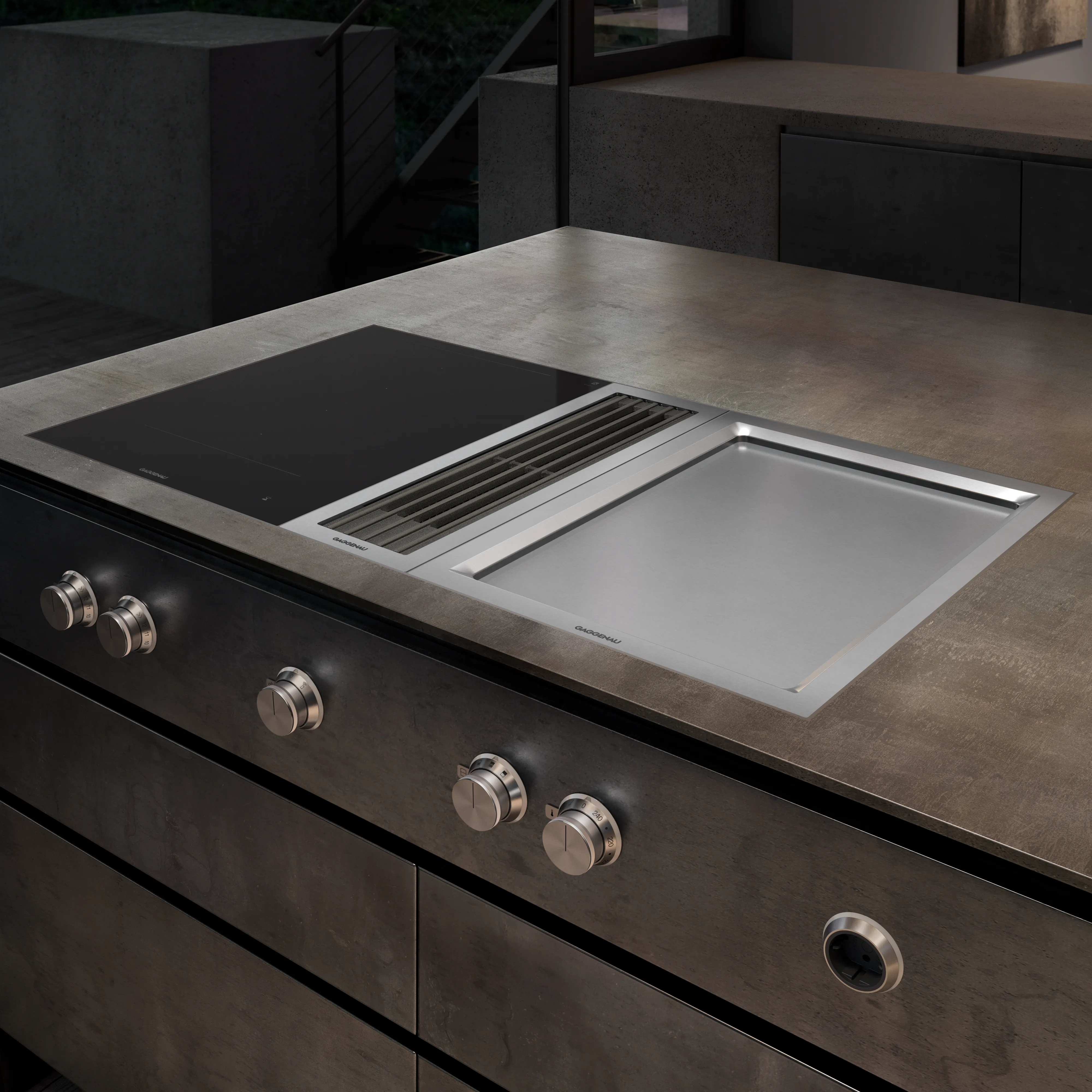
Two cooking zones combined as one large zone
Exact temperature control up to 240 °C
Cooking directly on the hard-chromed metal surface, without any pots or pans
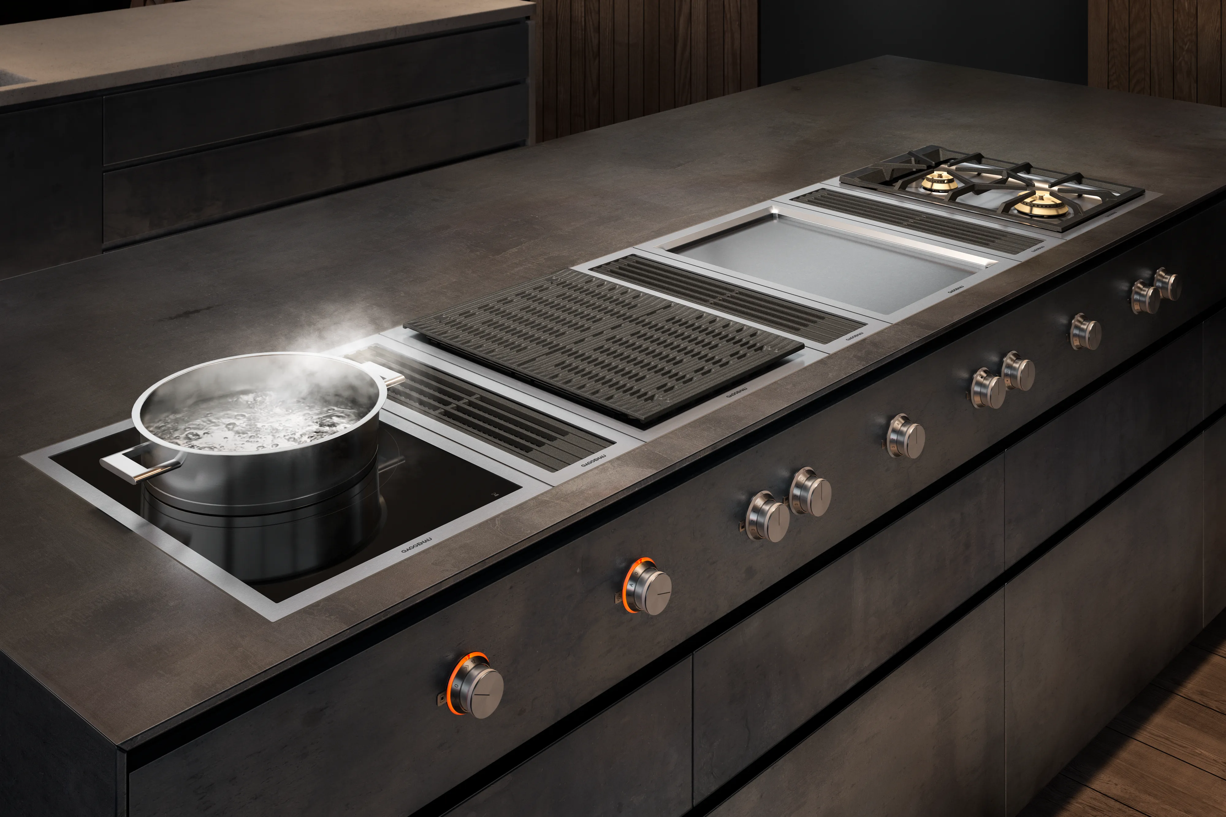
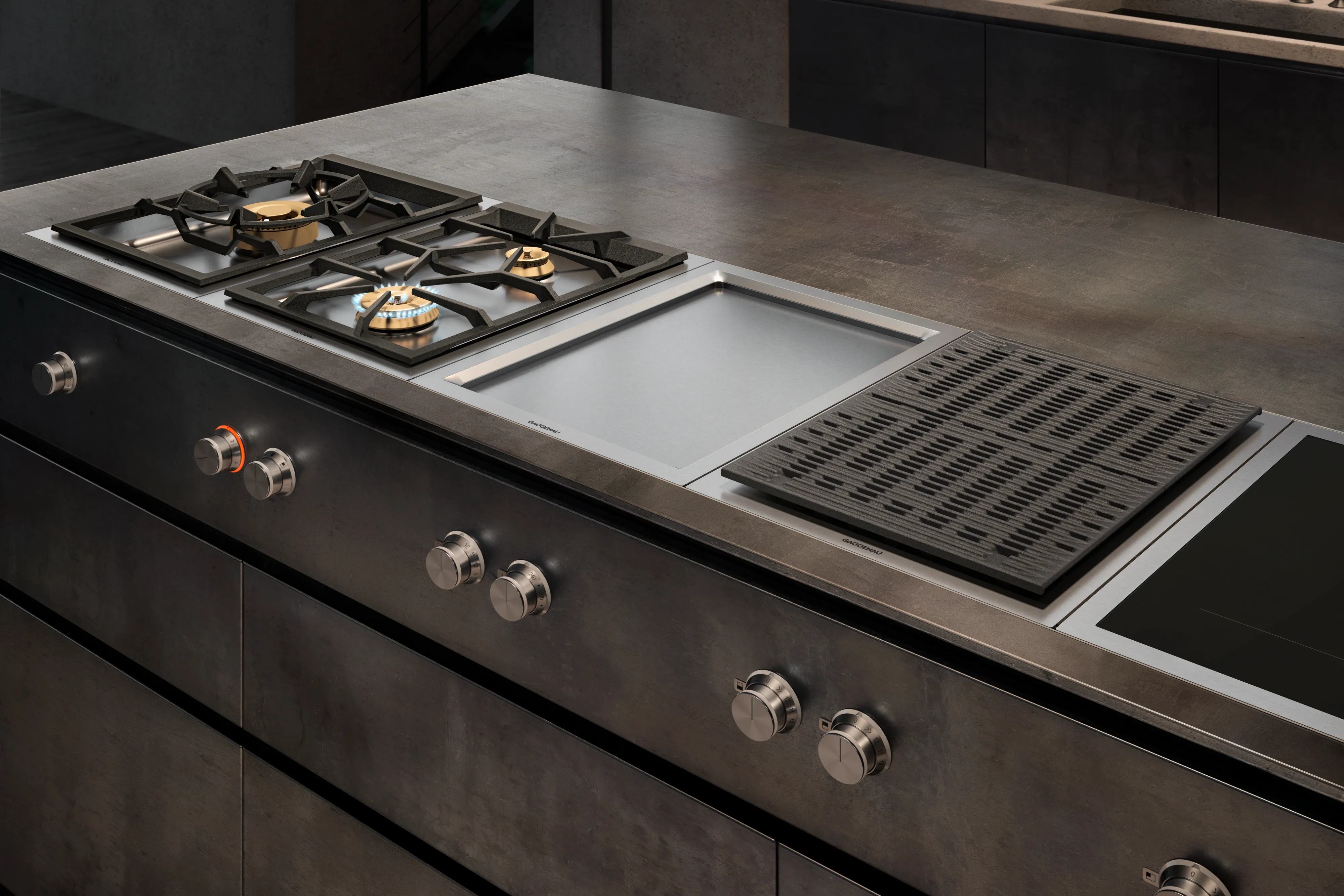
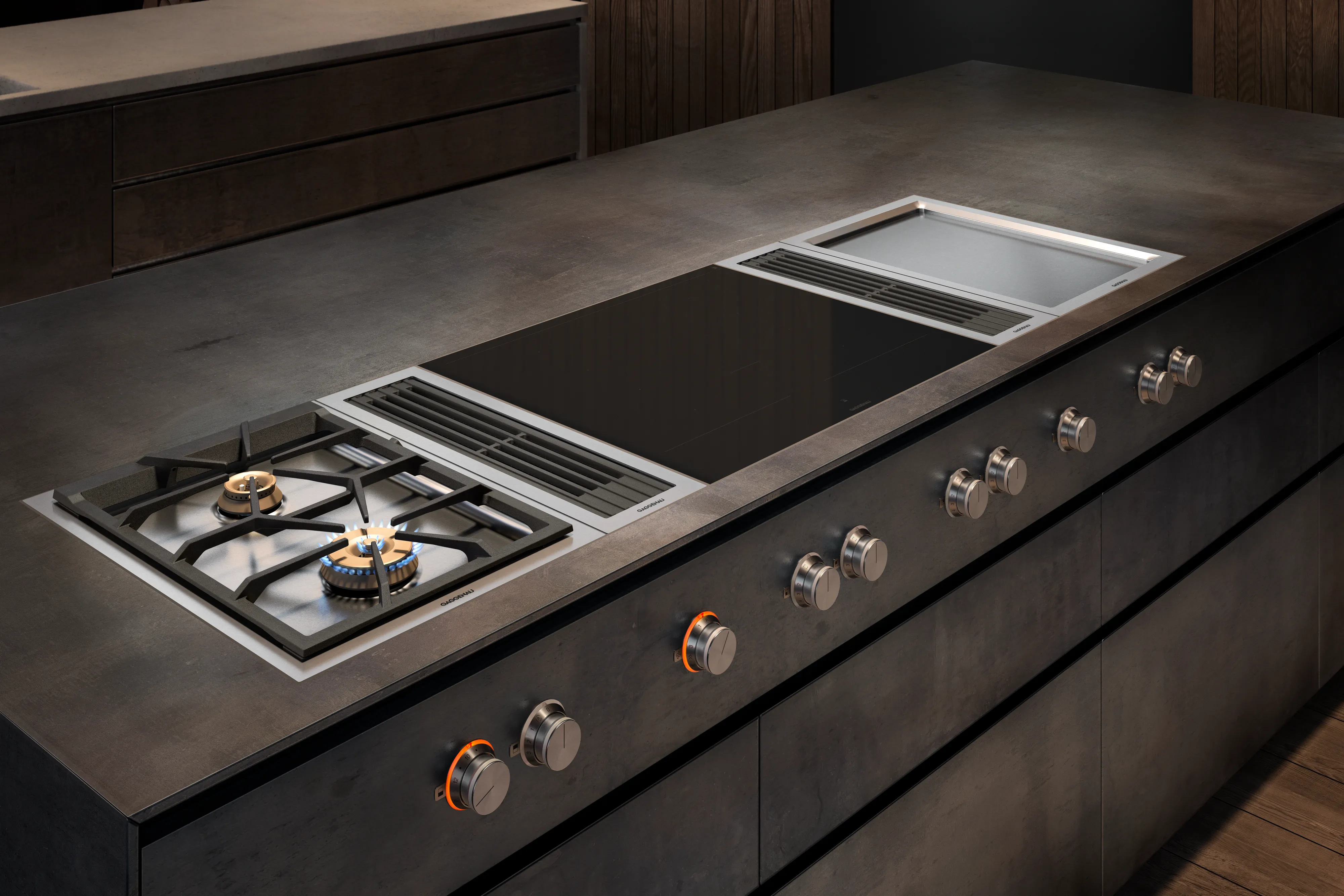
Can be combined perfectly with other Vario appliances of the 400 series
Specifications
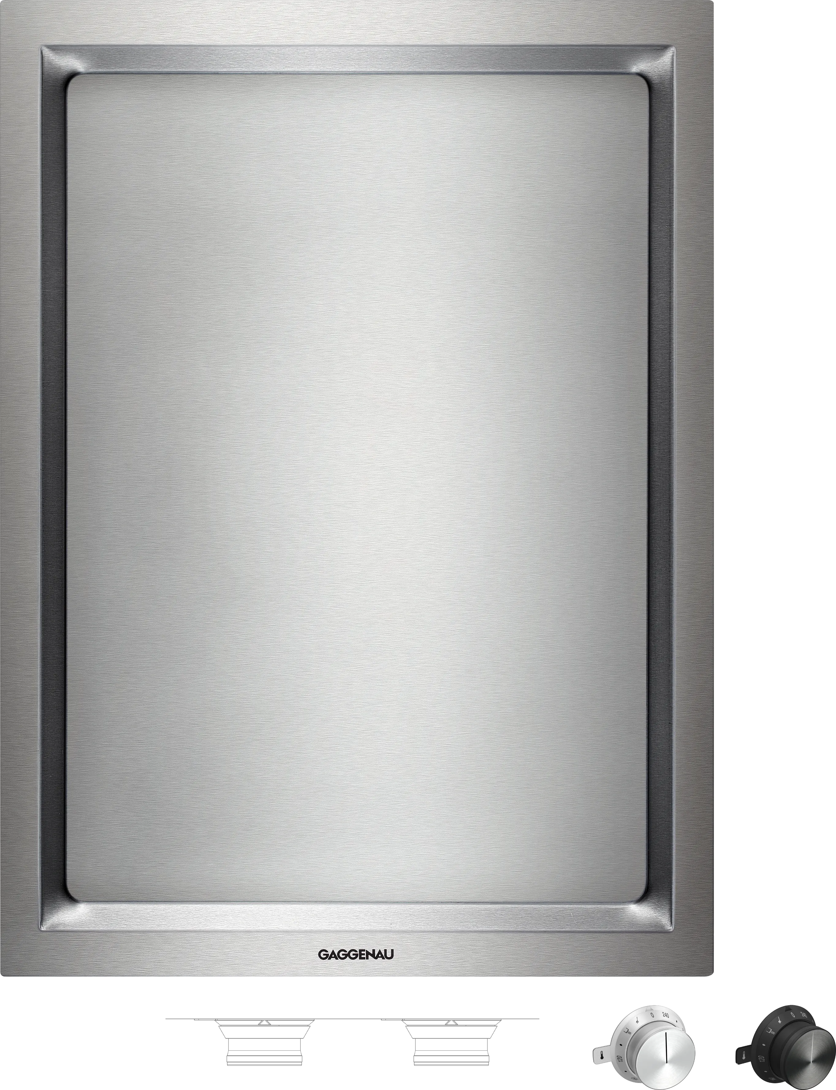
Cooking directly on the hard-chromed metal surface, without any pots or pans
Exact temperature control up to 240 °C
Optimum heat distribution
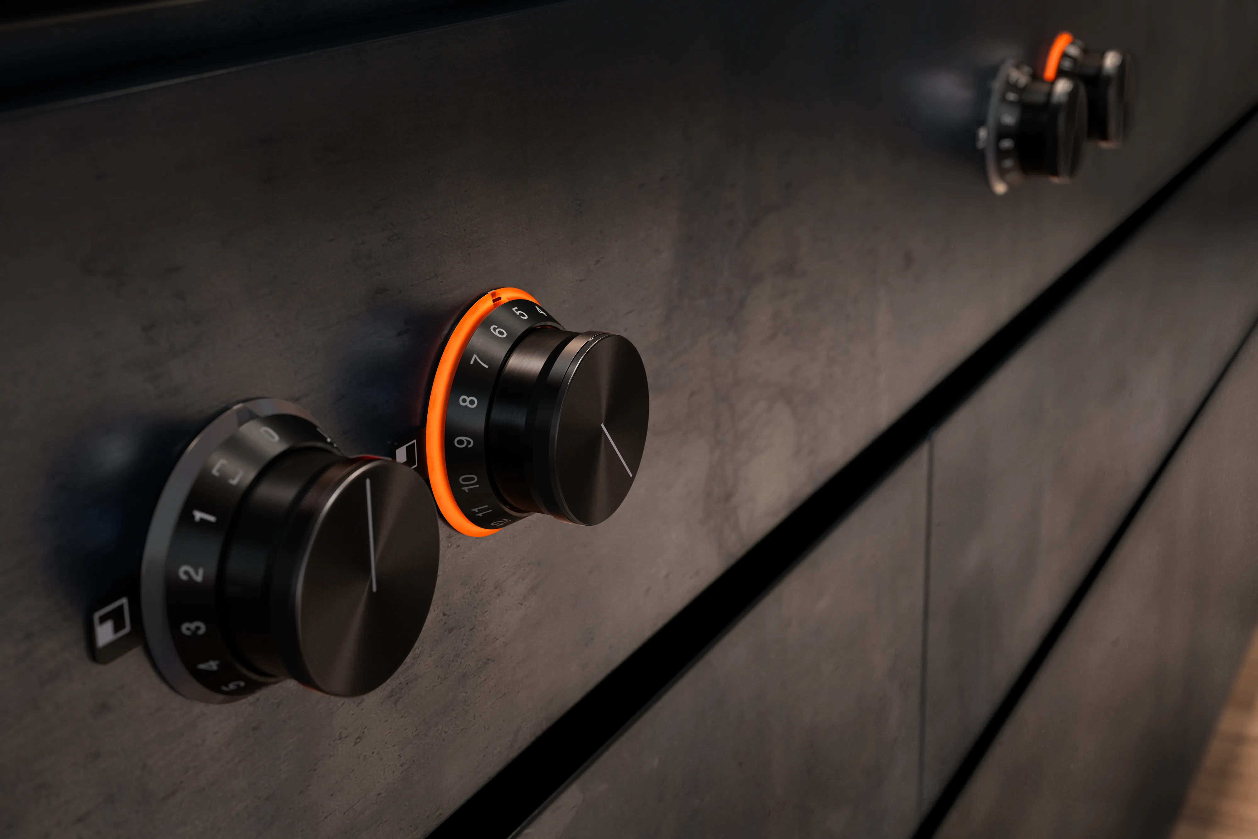
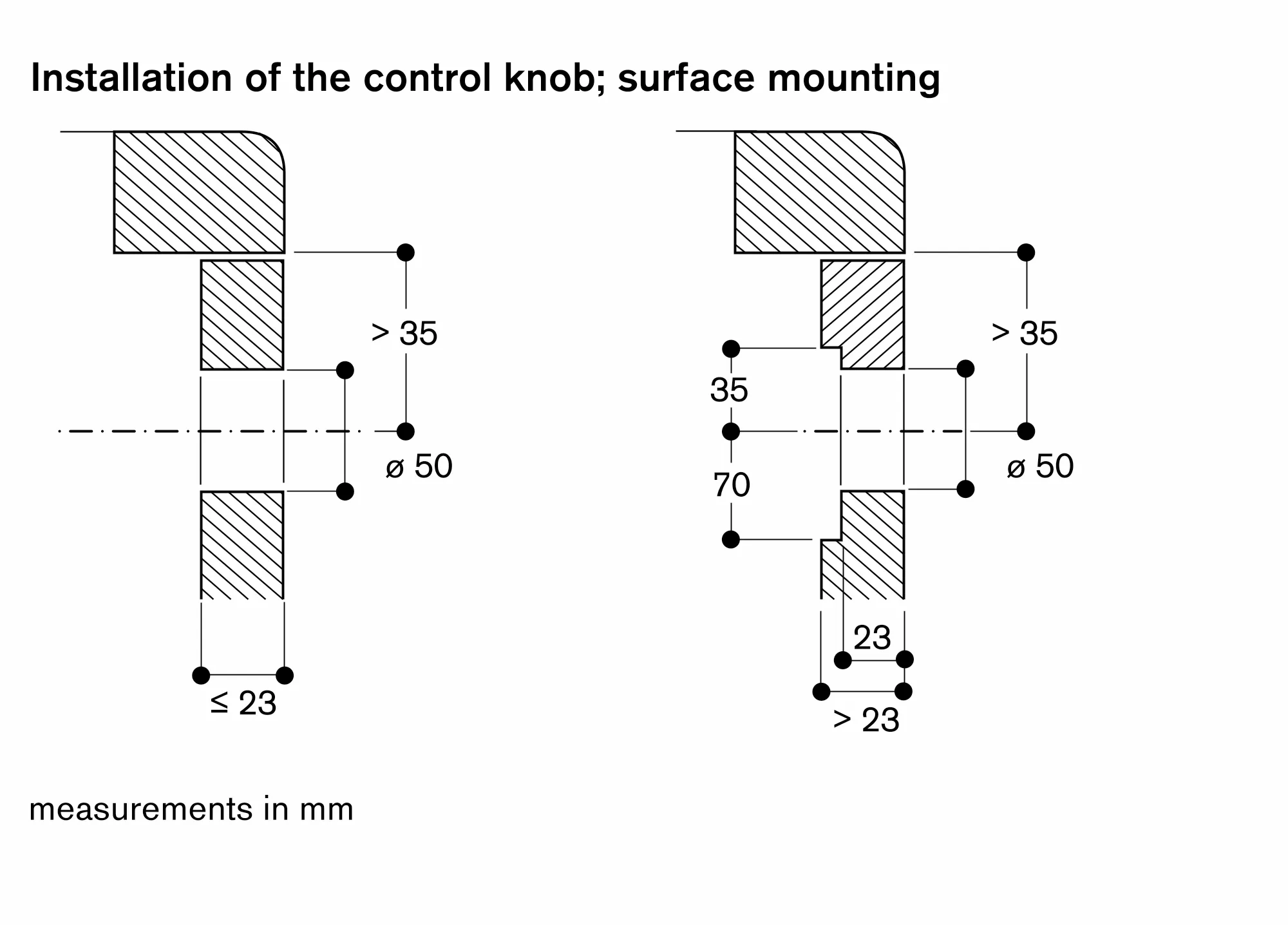
Solid stainless steel control knob or black control knob available; this must be purchased separately
Precision crafting of 3 mm stainless steel
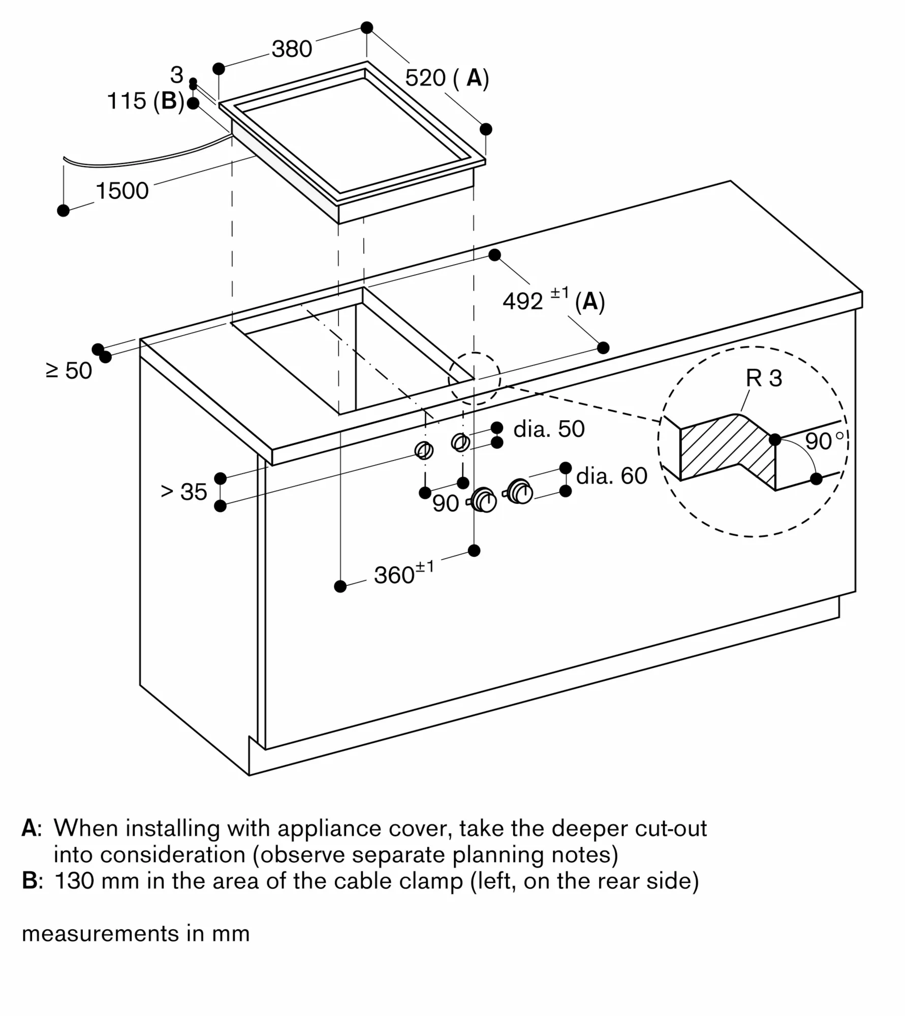
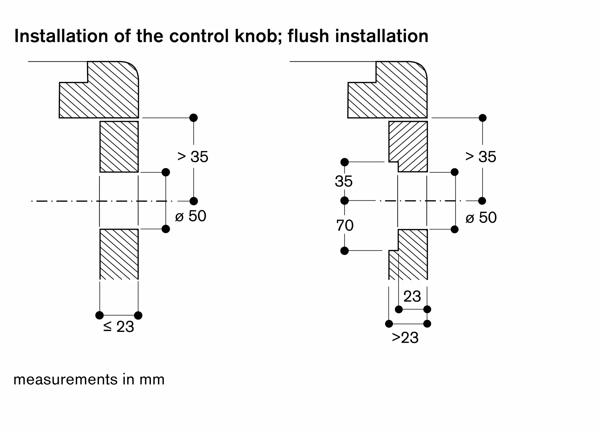
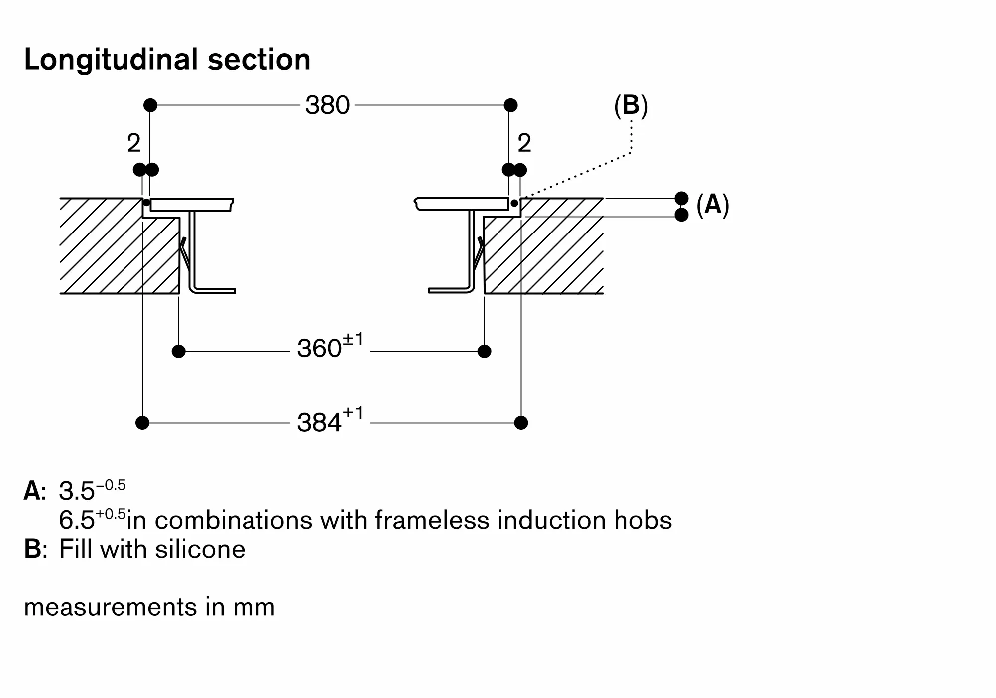
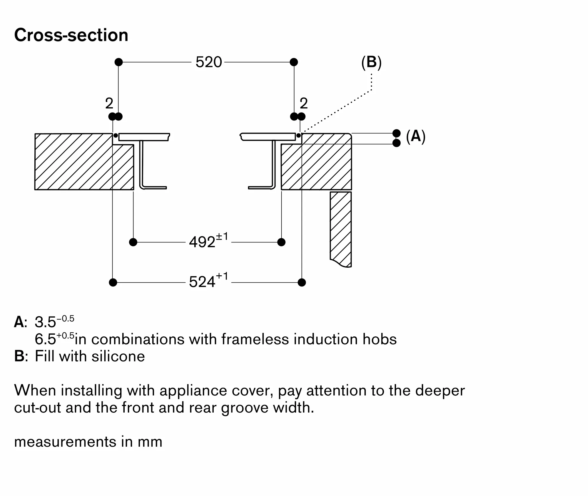
For surface mounting with a visible edge or for flush mounting
Can be combined perfectly with other Vario appliances of the 400 series
Usable area 31 x 44cm (WxD)
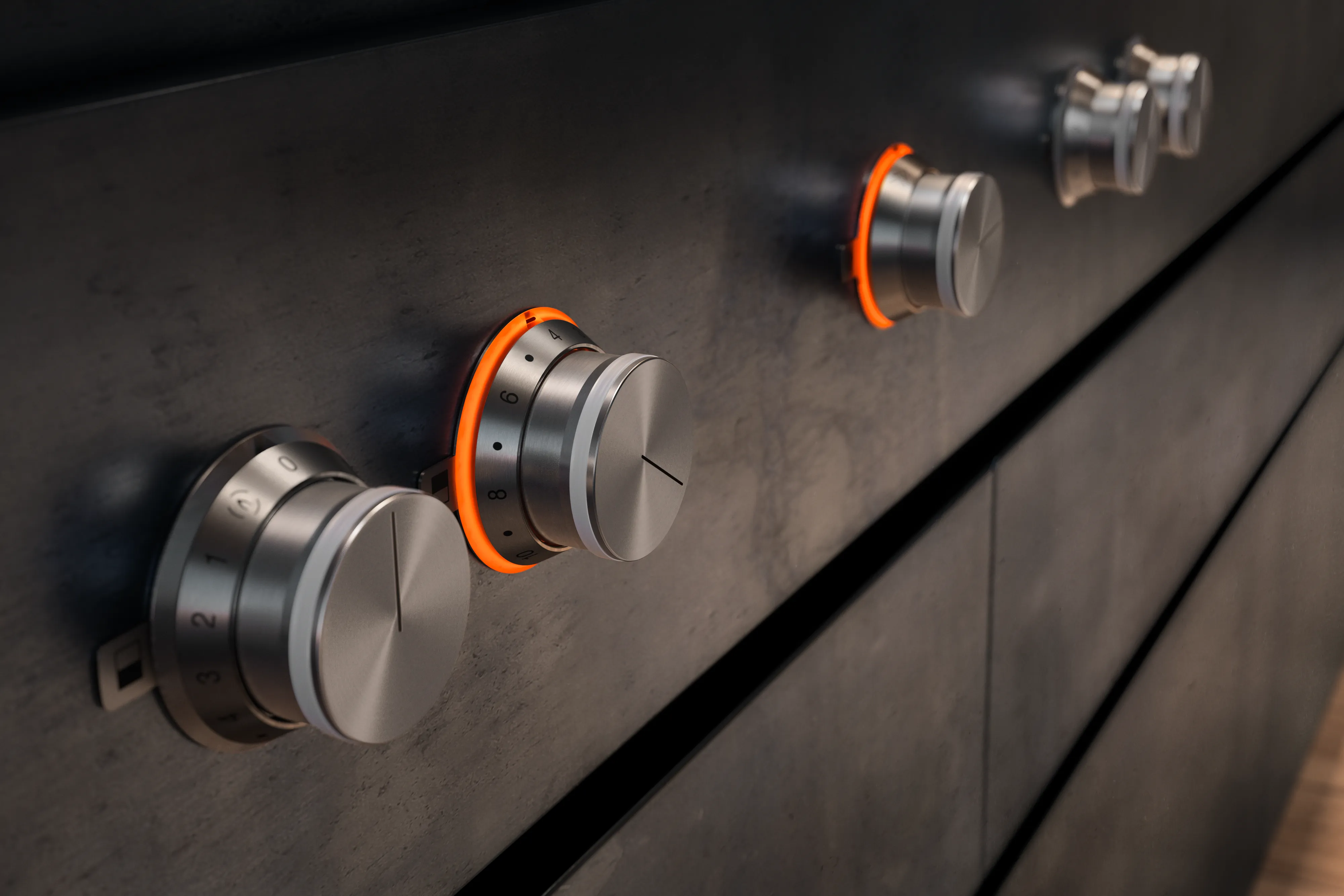
Control knobs with illuminated ring, cooking zone and temperature markings.
Electronic temperature control from 120 °C to 240 °C.
Two zones, each 1500 W, can be operated together as a complete surface or each half separately.
Keep warm setting.
Cleaning stage.
Easy to clean, similar to a cast pan.
Safety shut-off.
Pre-heat and residual heat indicator.
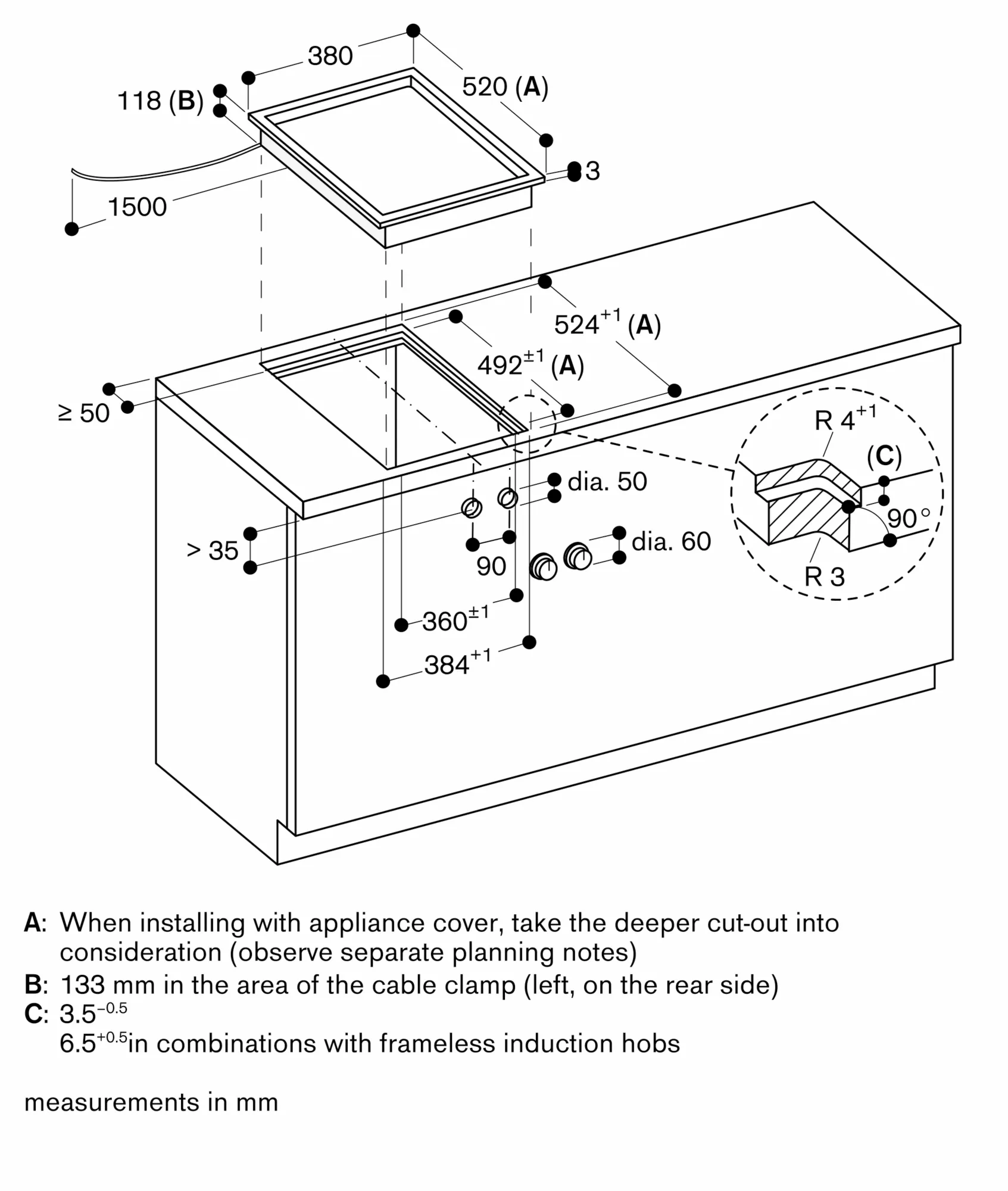
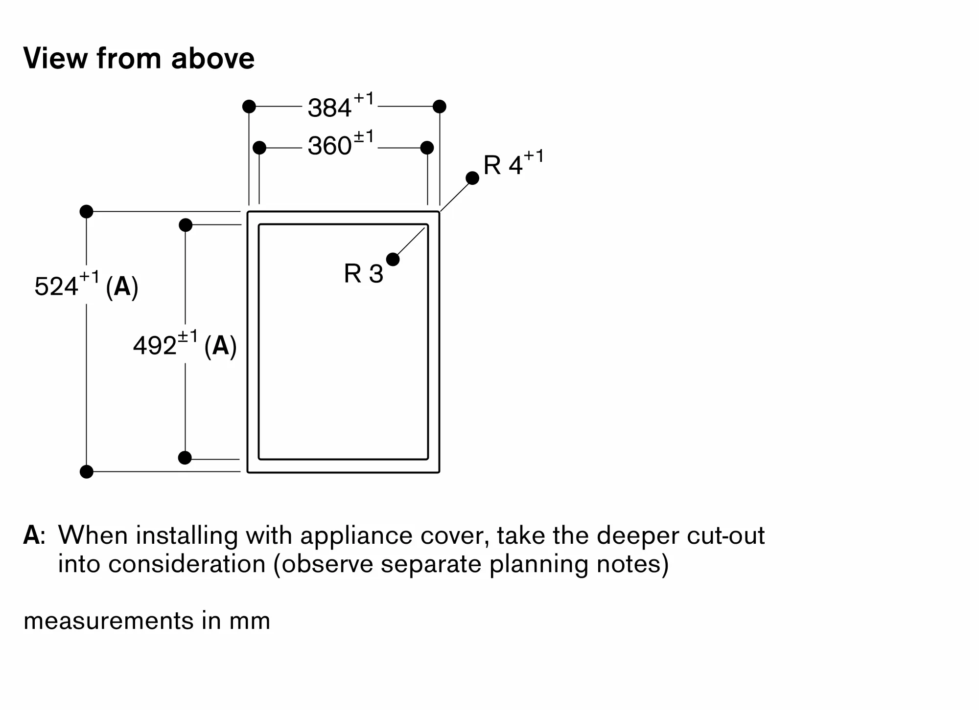
Depending on the type of installation (surface-mounted or flush-mounted, with or without an appliance cover), the specific location of the cut-out and the knob positions may vary.
If combining several Vario appliances of the 400 series, a connection strip VA 420 must be placed between the appliances. Depending on the type of installation, the corresponding connection strip must be provided.
The bearing capacity and stability, in the case of thin worktops in particular, must be supported using suitable substructures. Take into account the appliance weight and additional loads.
Additional instructions for flush mounting:
Installation is possible in worktops made of stone, synthetics or solid wood. Heat resistance and watertight sealing of the cut edges must be observed. Concerning other materials please consult the worktop manufacturer.
The groove must be continuous and even, so that uniform placing of the appliance on the gasket is ensured. Do not use discontinuous lining.
The joint width may vary due to size tolerances of the combinations and of the worktop cut-out.
If installing several appliances in individual cut-outs allow for a division bar of minimum 50 mm between the individual cut-outs.
A minimum lateral clearance of at least 40 mm from adjacent heat-sensitive furniture or contact surfaces must be observed or thermal insulation fitted.
Appliance can be snapped into the worktop from above.
Appliance weight: approx. 11.
Total connected load 3.0 KW.
Connecting cable 1.50 m without plug.
Manual and Documents
Find a local Dealer